Title: "[[Circuit-Design]]"
Author:
- AllenYGY
status: DONE
tags:
- NOTE
- CO
- CircuitDesign
created: 2024-01-16T21:03
updated: 2024-05-31T01:15Combinational Circuit Design
- Find Input and Output
- Truth Table
- K-Map Simplify
- Circuit
Sequential Circuit Design
Sequential Circuit Analysis
- Write Equations
- Clock equation 时钟方程
- Output equation 输出方程
- Drive equation 驱动方程
- State equation 状态方程
- List State
- 状态表
- 状态图
- 时序图
- Function
- 功能
- 是否自启动 存在无效状态则不能自启动
Example-1
Investigate the operation of the following circuit. Assume the initial state is 0000. Trace the outputs (the Qs) as the clock ticks and determine the purpose of the circuit. You must show your trace to complete your answer.
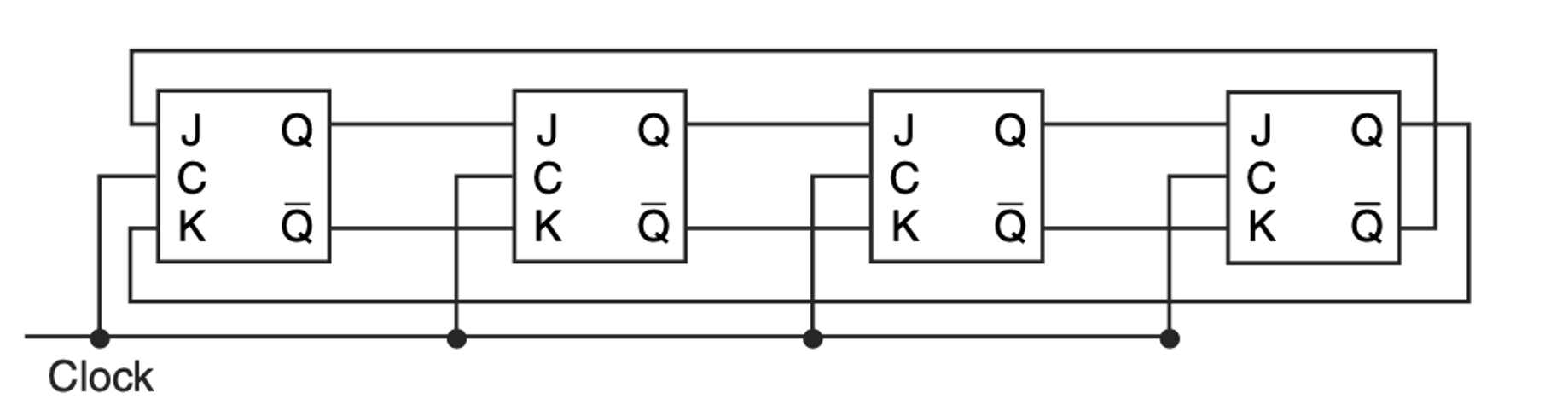
- Equation
- Clock equation
- Ouput equation
- None
- Dirve equation
- State equation
- Feature equation:
- Feature equation:
- Clock equation
- State
Valid status
Invalid status
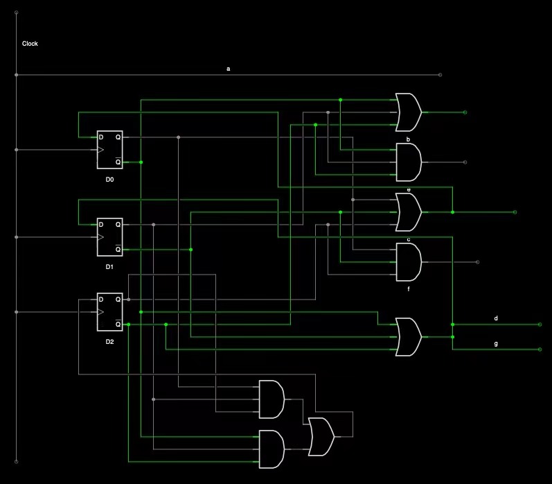
Design Sequencial Circuit
- State Diagram
- State Equation
- Output Equation
- Flip-Flop
- Circuit
Example-2
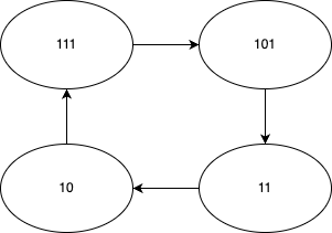
Design a finite state machine (FSM) for a counter that counts through the 3-bit prime numbers downwards and loop:
- You need to provide the state transition diagram. Assume that the state is stored in three D Flip Flops. Hint: The set of all 3-bit prime numbers includes 2, 3, 5 and 7. (4 points)
- State Diagram
- Design the sequential circuit for the counter. The circuit is driven by the clock. The output is a 7 segment LED display. The various digits from 0 through 9 can be displayed using a 7-segment display as shown in the following figure.