Title: "[[Finite-State-Machine]]"
Author:
- AllenYGY
status: DONE
tags:
- NOTE
- CO
- Lec7
created: 2023-11-03T00:59
updated: 2024-05-31T00:32The Concept of State
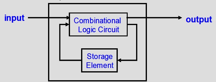
- The output of a sequential circuit is a function of the current input and the previous state 时序电路的输出是当前输入和先前状态的函数
- The state is stored in the storage element 状态存储在存储元件中
- The new state is also a function of the previous state and the current input 新状态也是前一个状态和当前输入的函数
Finite-State Machine 有限状态机
- A system is a finite state machine if it has the following five properties:
- A finite number of states 有限状态
- A finite number of external inputs 有限外部输入
- A finite number of external outputs 有限外部输出
- An explicit specification of all allowed state transitions 所有合法状态转换的明确规范
- An explicit specification of the rules for each external output value 每个外部输出值的规则的明确规范
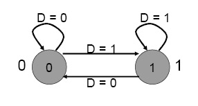
State Diagram
- Each state is shown with a circle, labeled with the state value – the contents of the circle are the outputs
- An arc represents a transition to a different state, with the inputs indicated on the label
每个状态都用一个圆圈显示,并标有状态值 - 圆圈的内容是输出
圆弧表示向不同状态的过渡,输入在标签上指示
- 3-bit counter
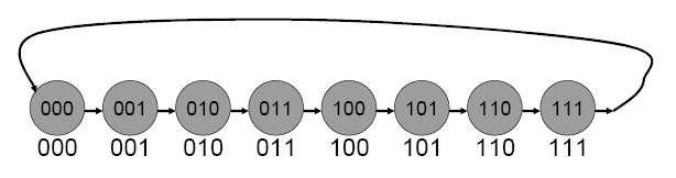
-
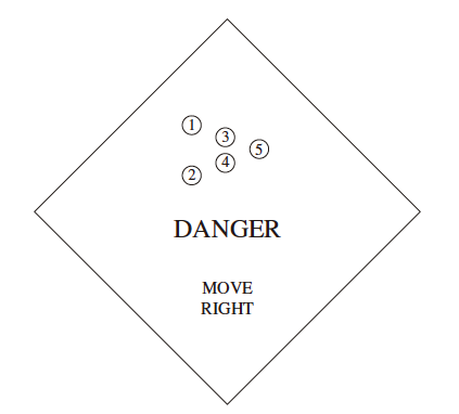
A Danger Sign
-
当开关断开
If the switch is turned off, all the lights are turned off and remain off -
当开关闭合
When the switch is in the ON position, the controller directs the lights as follows: During one unit of time, all lights will be off. In the next unit of time, lights 1 and 2 will be on. The next unit of time, lights 1, 2, 3, and 4 will be on. Then all five lights will be on. Then the sequence repeats: no lights on, followed by 1 and 2 on, followed by 1, 2, 3, and 4 on, and so forth.
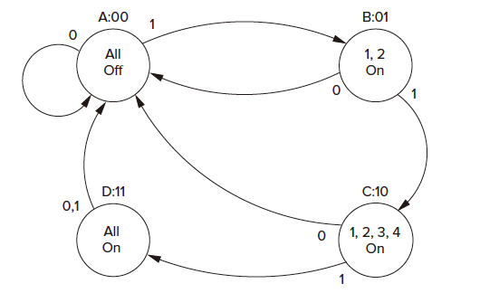
当All-on到All-off 输入0或1都可以实现而不是同时输入
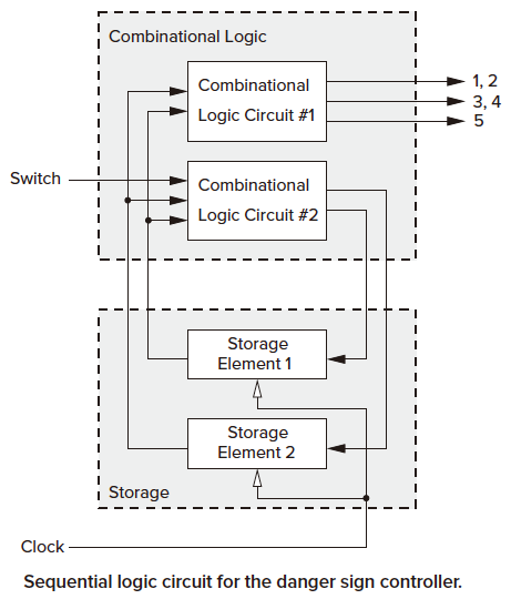
- First, the two external inputs: the switch and the clock. The switch determines whether the finite state machine will transition through the four states or whether it will transition to state A, where all lights are off. The other input (the clock) controls the transition from state A to B, B to C, C to D, and D to A by controlling the state of the storage elements. We will see how, momentarily.
- Second, there are two storage elements for storing state information. Since there are four states, and since each storage element can store one bit of information, the four states are identified by the contents of the two storage elements: A (00), B (01), C (10), and D (11). Storage element 2 contains the high bit; storage element 1 contains the low bit. For example, the danger sign controller is in state B when storage element 2 is 0 and storage element 1 is 1.
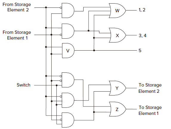
- Third, combinational logic circuit 1 shows that the on/off behavior of the lights is controlled by the storage elements. That is, the input to the combinational logic circuit is from the two storage elements, that is, the current state of the finite state machine.
- Finally, combinational logic circuit 2 shows that the transition from the current state to the next state depends on the two storage elements and the switch. If the switch is on, the output of combinational logic circuit 2 depends on the state of the two storage elements.
Turing Machine vs FSM
- A Turing machine is a finite state machine plus a tape memory.
- Each transition may be accompanied by an operation on the tape (move, read, write).
- Its total possible configurations are arbitrarily large, regardless of the size of the program; it expands towards infinity.
- Turing machines have more computational power than FSM.